How it works: A Biomass Boiler
April 2, 2013
BY Chris Hanson
Climbing oil prices and growing demands for cleaner energy sources inspired many boiler manufacturers to put a fresh spin on the traditional use of biomass to generate steam and heat. Today’s biomass boiler integrates modern technology to develop automatic systems that manage the process from emissions and air control to ash removal. With the modernization of steam boilers came hundreds of varieties, sizes and manufacturers, each one presenting new designs, cutting-edge technology, and a preview of what is yet to come. Coolidge, Ga.-based Hurst Boiler, the design of which is featured here, is one of those companies.
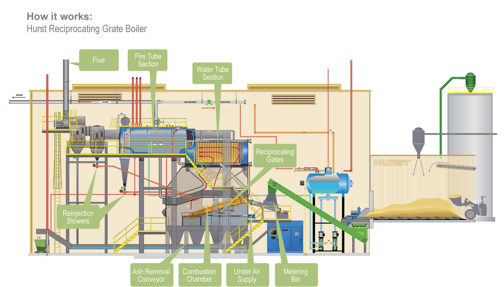
The general layout of a Hurst boiler system consists of three sections: a metering bin, a furnace and a hybrid boiler that together to produce steam that can be used for heating or generating power in a steam turbine. Manufacturers use a variety of methods to combust biomass feedstock. The Hurst system uses reciprocating fire grates to move feed stock through the boiler. Designed for use in large industrial settings such as factories, schools and greenhouses, it produces 3,450 to 10,000 pounds of steam per hour at 100 to 400 psi using biomass with a moisture content of 30 to 50 percent.
Fuel Metering Bin
At the beginning of the boiler process, fuel from the storage area is supplied via conveyor to the metering bin. The conveyor evenly disperses the fuel and transfers it into the combustion chamber through metering tubes. To determine the correct fuel proportion, the metering bin reacts to the conveyer system based on the current fuel load, system condition, and performance requirements.
The metering tubes inside the bin are specifically engineered to move the fuel and treat it before it lands in the feed auger. The tubes are built with rifling, a type of spiral cut, inside to allow fuel to land in the auger in a way that avoids blockage. Additionally, the metering tubes are equipped with thermo-actuated switches to prevent heat from the furnace igniting fuel inside the tubes. When the switch overheats, a solenoid valve activates, releasing water into the tube to diminish any heat working backwards in the system. The switch can be utilized to treat fuel and prevent premature burning to keep the furnace from overheating.
Advertisement
Into the Furnace
After the fuel is measured, it is then fed to the furnace section. With temperatures reaching up to 1,850 degrees Fahrenheit, the combustion chamber is encased in 13 inches of heat-retaining material, refractory walls, radiant wet arches, and mineral wool. At 9 inches thick, the bulk of the insulation material is insulation mud, and the last 4 inches consist of steel plating and other materials. The combustion chamber includes the reciprocating grates, above- and under-fire air intakes, and an ash removal system.
Inside the combustion chamber, fuel is fed from the metering bin to the reciprocating grates. The step-like, hydraulic grates alternate back and forth to move the fuel through the combustion zone. At the bottom of the steps, the resulting ash is dumped into the water-filled ash collector.
Under the grates is the under-fire air fan. The fan injects preheated air generated from the flue gases and combines with the solid fuel and volatile gases to release heated gas upwards through to the refractory chamber. The under-fire fan is governed by the zone damper slides, and accounts for fluctuating conditions to maintain a constant steam supply.
As heat and volatile gases move up to the refractory chamber, they combine with air from an over-fire wall jet nozzle. This causes complete combustion of volatile gases and produces maximum heat from the fuel around the refractory arch.
Advertisement
The refractory chamber is located above the combustion area. It is the largest part of the furnace and holds the 1,832 F furnace gases for a set amount of time to ensure complete combustion and breakdown of hazardous hydrocarbons. As the burning gases move up and out of the refractory zone, it reaches the next section of the operation, the hybrid boilers.
Hybrid Boilers
The boiler consists of water tube and fire tube sections, which are insulated with 2 inches of mineral wool and covered with sheet steel lagging. It is this coating that keeps the boiler from reaching temperatures of 120 F. The first half of the hybrid boiler, the water tube section, receives the initial heat from the burning fuel below. The water section is gas tight and comprised of arched water tubes to supply heated water for the fire tube section.
The burning gases leave the water tube and travel through horizontal pipes inside the fire tube. Each tube is surrounded by water, and evaporates as the heated gas travels and doubles back through the tubes. From the fire tube section, steam travels through the top to be used as heat in buildings, or to power steam generators. At this stage, any heavy particulates, or fly ash, are dropped into a blower system that deposits them into the ash collector. The rest of the exhaust gas moves to the multicyclone collector.
Collection Tubes
The multi-cyclone collector is located past the fire tube section and consists of 9-inch collection tubes. Inside them are spinners that collect even more particulates. Like in the fire tube section, the fly ash goes through a blower system back to the combustion chamber and ultimately the ash collection system. Finally, the heat that the exhaust gas contains is used by the economizer mounted on top of the exhaust stack to preheat water for the feed water storage device.
Ash
Much of the heavier waste, such as particulates and ash from burned feed stock, is deposited into the ash conveyer system, which consists of a water-filled trough that saturates ash to prevent dust escaping to the heat exchanger. As it sinks to the bottom, the ash is pulled by a chain outside of the furnace. The water is drained using an inclined slope and the left-over ash is deposited onto another convoyer to be used as fertilizer or other uses.
Author: Chris Hanson
Staff Writer, Biomass Magazine
701-738-4970
chanson@bbiinternational.com
Upcoming Events