Managing Biogas Storage and Retrieval

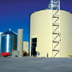
PHOTO: NOBLEHURST GREEN ENERGY
January 22, 2016
BY Bruce Smith
Stored biogas shouldn’t be treated as a static inventory only to be used during temporary upset conditions. Successful management begins with proper sizing of the gas holder, and continues with controlling process options to maintain an appropriate inventory in the gas holder. This article is written from the perspective of maintaining a near-atmospheric pressure biogas inventory while operating an anaerobic digester to produce methane-rich biogas to fuel combined-heat-and-power (CHP) generator systems or to fuel boilers. Many of the principles discussed can be applied to other biogas systems as well.
Gas Holder Basics
The purposes of a gas holder are to provide biogas storage to offset temporary imbalances between gas production and gas use, and to establish a biogas reserve. Since they have flexible walls, gas holders operate within a range of volumes, rather than a fixed volume. When gas is being produced in a biodigester faster than it is being consumed, excess can accumulate in the gas holder. When gas is being consumed faster than it is being produced, stored gas can be drawn out of the holder to supplement production and satisfy the biogas consumer. In this manner, the gas holder becomes a buffer for short-term process imbalances.
Walls of a typical gas holder are flexible in the sense that they can distort so that the containment volume will match the volume of biogas inside, with little change in internal pressure. Gas holder membranes collapse when emptying and inflate when filling, similar to a balloon, except the membranes do not stretch and internal pressure does not vary significantly. These design principles are important. Remote, bladder-style holders consist entirely of membrane material, all of which flexes with changing inventory. This style can either be protected by a rigid shell or be installed without a shell. Integral gas holders consist of flexible membranes sealed to a rigid open-top vessel. Only the membrane is allowed to deform in these designs; the rigid vessel can be used to contain digestate. These two configurations are common;other styles exist.
To fulfill their purpose, remote gas holders are connected to the pipeline between the vapor space of the biodigester and the biogas consumers. Typically, a simple pipeline tee is used to permit biogas to flow to or from the gas holder to best balance supply and demand cycles of the biogas system.
Sizing Considerations
The volume of a gas holder has practical limits related to gas supply-and-demand variations, as well as economics. The minimum volume contained in a gas holder needs to address a situation when biogas production drops drastically. At such times, the operator will need to initiate process control measures either manually or automatically. These measures can include reducing consumption of selected gas users, stopping gas users, diverting to backup fuel sources, or other options. Then, the minimum gas holder is whatever volume is required to give the operator enough time to execute deliberate, controlled process changes in response to the situation. Typically, this reserve volume will be equivalent to one or several hours of biogas consumption. Generous time allowances translate to larger volumes, larger space requirements, and larger capital costs, so economics will influence this sizing factor. Well planned system controls should alleviate the operator from needing excessive reserve volumes. If the minimum volume selected is too small, the operator will be faced with frequent process upsets that might otherwise have been avoided.
Maximum gas holder volume relates to imbalances in gas production compared to gas consumption. As long as the feed stream and digester conditions do not change, biodigesters produce a relatively constant flow of biogas. Daily rates may vary several percent, but the average rate can be relatively constant on an annual basis. In some systems, gas usage is fairly constant on a daily basis. Rarely, though, does gas generation exactly match gas use. Some imbalance can be buffered by modulating fuel systems at the user. Much of the imbalance is allowed to be absorbed at the gas holder. As stated earlier, the gas holder will inflate when supply exceeds demand and deflate when supply lags demand. All of this variation needs to occur above the minimum volume required for a controlled shutdown. For instance, if a selected digester system requires an emergency backup volume of 2,000 cubic feet, and the annual supply/demand imbalance can reach up to 400 cubic feet, then the operating range of the gas holder should be 2,000 to 2,400 cubic feet. Allowing a safety factor to prevent frequent gas holder overpressure situations, the total gas holder volume for this system might be specified to be 2,800 to 3,000 cubic feet.
Biodigesters utilizing a boiler (biogas-fired heater for heat transfer fluid) for process heating can exhibit some of the more extreme gas holder volume swings. Process heating can include using heat transfer fluid from the boiler to heat the digester, reception tank, digester feed streams, building spaces, hot water supplies and other systems.
Additional Considerations
If process heating is supplied exclusively from a CHP unit, cyclic daily heat demand often needs to be accounted for in the design of heat transfer systems, rather than planning to modulate consumption at the CHP unit. CHP units can vary heat output, but this results in varying output of electrical power. Frequent radical changes in CHP power output are usually undesirable.
Gas consumption can change along with annual seasonal changes. For instance, digesters in cold climates require more heat during winter months. If a boiler is the primary heat source, it will require more biogas fuel in winter. With more fuel directed to the boiler, other biogas users will need to be operated at lower capacity or shut down. If a CHP system is the primary heat source, the system will need to maximize heat output. If there are other types of systems consuming biogas and reserve capacity in the CHP system, the other operations may need to be scaled back or shut down to increase output from the CHP units. If the CHP system is the sole biogas consumer, heat that would otherwise be used elsewhere in warmer months will need to be redirected to keep the digester warm. These changes need to be managed to prevent the gas holder inventory from emptying or overfilling. Note that fuel-to-heat conversion is in the range of 80 percent in boilers and 35 to 40 percent for CHP units. Therefore, increasing boiler fuel supplies by a given volumetric flow yields about twice the heat output increase than an equal increase to CHP units. These relationships are important to consider when sizing the gas holder.
A flare can be used to help manage biogas supplies when the gas holder is nearly full and biogas production exceeds consumption. In these cases, biogas can automatically be burned in an approved flare. This prevents release of methane into the atmosphere.
If biogas is allowed to overfill the gas holder, the excess gas vents to the atmosphere through a pressure relief vent equipped with a flame or detonation arrestor. This is done for safety purposes. An owner should minimize the volume of excess biogas that is allowed to vent from a gas holder for both economic and environmental reasons. A biogas discharge limit may be stipulated in air emission permit documents. If the gas holder inventory drops to near zero and there is a risk of rupturing a membrane or tank, a vacuum relief vent may need to be installed on the gas holder. Such a provision would permit air to enter the gas holder and create a potentially hazardous atmosphere inside the holder and other parts of the biodigester system, so the installation should be done with appropriate fire protection measures.
Design of a remote gas holder needs to account for condensate dropping out of the biogas during storage. The relative humidity of biogas leaving the digester is saturated with water vapor at 100 percent relative humidity. Unless the gas is dried, the relative humidity remains at 100 percent until it is used. In almost all cases, the temperature of biogas is lower in transfer piping and gas holder than in the digester. Absolute humidity of saturated biogas is lower at cooler temperature than at elevated temperatures. The net effect is that moisture condenses and flows as a liquid to the nearest low point in the gas system. The gas holder should not be the low point in the biogas system. Instead, piping connected to the gas holder is typically connected at the bottom of the gas holder and is sloped to permit condensate to drain to a system condensate collection point.
When digester feed streams or conditions are altered, biogas output can increase or decrease enough to warrant process changes.
Modeling and Controls
Biogas holder size and gas management options can be predicted by simulating operations using a mathematical model of the facility. To do this, one can input operational characteristics into a model developed for the specific process cycles unique to the plant. Important characteristics include, but are not limited to: biogas production and methane content; summer and winter heating requirements; boiler burner size and turndown limits; CHP heat recovery characteristics; fuel consumption and turndown limits of CHP generators; and schedule of operating cycles. This does not require proprietary software; common spreadsheet software is adequate. Once all of the data is entered, charts can be used to represent how biogas inventory is affected by process changes. Information gleaned from this type of modeling may lead to digester process design changes.
It is important to keep track of the volume contained in a gas holder. Clearly, corrective measures need to be taken when level instruments indicate that inventory approaches high or low limits. Additionally, level indicators can display gradual upward or downward volume trends. Some of these types of changes can be predicted by modeling prior to startup.
Author: Bruce R. Smith
Project Manager, Sidock Group
231-722-4900
bsmith@sidockgroup.com
Advertisement
Advertisement
Advertisement
Advertisement
Upcoming Events